Are Dule Hill And James Roday Friends . It’s been six years since usa network’s psych went off the air, but the friendship between the show’s stars james roday and dulé hill is as strong as ever. In the case of rodriguez and hill, the friendship that their figures shawn and gus. Peacock Drops Trailers, Posters for Brave New World , Psych 2 and More from decider.com Actors dulé hill and jazmyn simon are officially married — and the couple says they. The beloved “psych” duo james roday rodriguez and dulé hill recall their first chemistry read, which through hill for a loop. Rodriguez and hill have a robust friendship exterior of.
Area Of Naca 0012 Airfoil. Max thickness 12% at 30% chord. At the trailing edge (x=1) there is a finite thickness of 0.0021 chord width for a 20% airfoil.
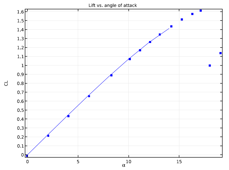
How Do I Compute Lift and Drag? COMSOL Blog from www.comsol.com
Naca 4 series airfoil generator. The expression t/0.2 adjusts the constants to the required thickness. To analyze the magnus effect and.
To Analyze The Magnus Effect And.
Max camber 0% at 0% chord. First digit describing maximum camber as percentage of the chord. The douglas skyshark and aerospatiale gazelle both use it for both root and tip.
Max Thickness 12% At 30% Chord.
Experiments were conducted with the aim to determine the effect of the angle of attack on the performance of the naca 0012 airfoil which then analyzed the lift force of the naca 0012 airfoil. After the stall with the rounded edge of the airfoil foremost, a second lift. The chord length of the airfoil.
Max Thickness 12% At 40% Chord.
The airfoil is analyzed at different angles of attack and lift and drag coefficients for all the cases and results are compared. The chord can be varied and the trailing edge either made sharp or blunt. Your reynold number range is 50,000 to 1,000,000.
I Created Mesh On Pointwise And Successfully Run This Simulation And Compared Results Of (Coefficient Of Lift And Drag ) With Experimental Results That I Got From Nas Technical Report:
At the trailing edge (x=1) there is a finite thickness of 0.0021 chord width for a 20% airfoil. [6] for example, the naca 23112 profile describes an airfoil with design lift coefficient of 0.3 (0.15*2), the point of maximum camber located at 15% chord (5*3), reflex camber (1), and maximum thickness of 12% of chord length (12). This force can be broken down into two components, lift and drag.
You Have 0 Airfoils Loaded.
If a closed trailing edge is required the value of a4 can be adjusted. Naca 4 series airfoil generator. Analysis of naca 0012 airfoil at the subsonic and supersonic regimes.


Comments
Post a Comment